
Material & Actuator Selection for V Port Ball Valves
1. Material selection of V port ball valves
Technical Drawing
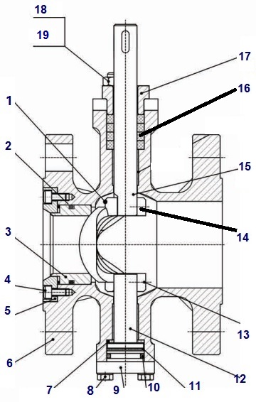
Technical G.A drawing of a V port ball valve, trunnion mounted with RF flange ends.
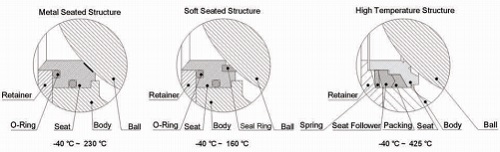
Seating designs for V port ball vlve: metal seated, soft seated, high-temp. structure.
See more specifications of trunnion mounted V port ball valves. Also see the dimensional data sheets for RF flanged type and wafer type respectively.
Material Specification
| Item No. | Part Name |
|---|---|
| 1 | Ball |
| 2 | O-Ring |
| 3 | Seat |
| 4 | Screw |
| 5 | Retainer |
| 6 | Body |
| 7 | Gasket |
| 8 | Bolt |
| 9 | Bottom Cap |
| 10 | O-Ring |
| 11 | Gasket |
| 12 | Bottom Stem |
| 13 | Bearing |
| 14 | Bearing |
| 15 | Upper Stem |
| 16 | Stem Packing |
| 17 | Gland Flange |
| 18 | Bolt |
| 19 | Nut |
| Part Name | Material |
|---|---|
| Body | ASTM A216 WCB, ASTM A217 WC6, ASTM A351 CF8/ CF8M |
| Stem | ASTM A182 F304/ F316 |
| Retainer | ASTM A351 CF8/ CF8M |
| Seat | PTFE, SS304, SS316, SS316+STL, SS316+Cr |
| Packing | PTFE, Graphite |
| O-Ring | NBR, Fluorin Rubber |
2. Flow characteristics and actuator selection
Flow Characteristics
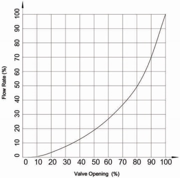
The flow characteristic curve of V port ball valves: Equal Percentage.
| Flow Coefficient Cv | ||||||||||||||
| DN | 25 | 32 | 40 | 50 | 65 | 80 | 100 | 125 | 150 | 200 | 250 | 300 | 350 | 400 |
| Cv | 27 | 47 | 70 | 110 | 170 | 280 | 410 | 750 | 980 | 1720 | 2900 | 3800 | 7000 | 9800 |
| DN | 25 | 32 | 40 | 50 | 65 | 80 | 100 | 125 | 150 | 200 | 250 | 300 |
| Soft Seated | 6.4 | 6.4 | 6.0 | 4.8 | 3.2 | 3.0 | 2.4 | 1.2 | 1.3 | 1.1 | 0.9 | 0.6 |
| Metal Seated | 6.0 | 5.8 | 4.2 | 3.7 | 2.4 | 2.3 | 1.4 | 1.2 | 0.9 | 0.8 | 0.7 | 0.4 |
Pneumatic Actuator
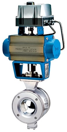
A wafer type V port ball control valve, 150LB 6″, trunnion mounted with pneumatic actuator.
| Function | Angle-travel for throttling or on-off services. |
| Structure | Pneumatic Cylinder Type, Spring Return Type(Double Acting) |
| Actuator Type | Direct Action, Reverse Action. |
| Air Supply | 0.6 MPa(G) |
| Connection | Rc 1/4" |
| Action | Direction action: air to valve shut; Reverse action: air to valve open. |
| Intrinsic Error | ±2%(with positioner), ±5%(without positioner) |
| Hysteresis | 1%(with positioner); 5%(without positioner) |
| Hysteresis Erro | 1%(with positioner); 3%(without positioner) |
| Ambient Temp. | -20~80℃ |
| Accessaries | E/P, P/P-Positioner; Air-Set; Solenoid Valve; Limit Switch, etc. |
| Double Acting | PAD075 | PAD092 | PAD105 | PAD125 | PAD140 | PAD160 | PAD190 | PAD210 | PAD270 |
| Torque(N*m) | 60.4 | 136.3 | 197.3 | 308 | 526 | 802 | 1292 | 1579 | 2463 |
| Single Acting | PAS091 | PAS125 | PAS140 | PAS190 | PAS210 | PAS240 | PAS270 | PAS300 | PAS400 |
| Torque(N*m) | 71.2 | 159.5 | 281.7 | 706 | 860 | 1270 | 2033 | 2563 | 3026 |
Electric Actuator
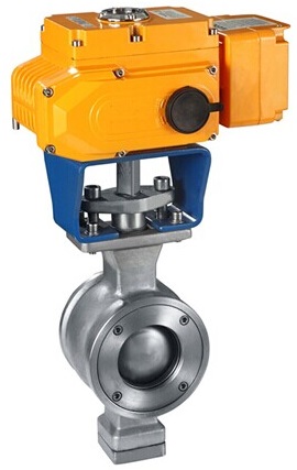
A wafer type V port ball control valve, electric actuator operated, 4″ 300LB.
| Function | Electric actuators for throttling and on-off applications. |
| Structure | Solid State Electric Type |
| Power Voltage | 220 VAC |
| Resolution | ±1% |
| Hysteresis | 2% FS |
| Ambient Temperature | -20~80℃ |
| Optional Accessories | Torque Switch, Space Heater, Junction Box, Potentiometer, etc. |
| Actuator Type | EA010 | EA020 | EA040 | EA060 | EA100 | EA150 | EA200 | EA250 |
| Torque(N*m) | 100 | 200 | 400 | 600 | 1000 | 1500 | 2000 | 2500 |
| Travel Angle | 0~90° | 0~90° | 0~90° | 0~90° | 0~90° | 0~90° | 0~90° | 0~90° |
| Acting time(s) | 30 | 30 | 30 | 30 | 30 | 45 | 60 | 75 |
Actuator Selection
| DN | Pneumatic Actuator | Electric Actuator | |
| Double Acting | Single Acting | ||
| 25 | PAD075 | PAS091 | EA010 |
| 32 | PAD075 | PAS091 | EA010 |
| 40 | PAD092 | PAS125 | EA010 |
| 50 | PAD092 | PAS125 | EA010 |
| 65 | PAD092 | PAS125 | EA010 |
| 80 | PAD105 | PAS140 | EA020 |
| 100 | PAD105 | PAS140 | EA020 |
| 125 | PAD125 | PAS140 | EA040 |
| 150 | PAD140 | PAS192 | EA060 |
| 200 | PAD160 | PAS200 | EA100 |
| 250 | PAD190 | PAS240 | EA150 |
| 300 | PAD210 | PAS270 | EA200 |
| 350 | PAD270 | PAS270 | EA250 |
| 400 | PAD270 | PAS270 | EA250 |
CATEGORY AND TAGS: